Extending Zigbee Range with CC2530 + CC2591 #465
Comments
and now I've just replaced the antenna by a 9db wifi one. don't know about CC2630, i've been looking at cc2538+cc2592 but there's no support for either of them yet |

|
the 9db antenna test is a failure, worst rssi. |
|
Hi @lolorc , I see that the firmware you propose is not the one mentioned on the wiki. What's the advantage of the one that you recommend? Which usb2serial converter are you using? I believe the #291 comment mixed up RX and TX. And does not mention 3.3v to VCC on the 2530, I assume that is needed as well to power the board? |
|
I think it's just matter of updating the wiki :) About powering the cc2530 from the rpi, as far as I remember the rpi is not able to provide a lot of current on its 3.3V output. My usb2serial converter is a FT232BM clone, I power the cc2530 from it with its 5V output, and the serial levels are ttl ones, 3.3V. |
|
Flashed successfully and it's working correctly in combination with the 3.3v from the Pi, thanks. |
|
The range is still not as good as the Xiaomi Gateway though. |
|
This is failing for me, can someone give some advice? My error: My steps:
|
|
@HKC001 Execute |
|
I don't have any ttyS* port The tty word is in pink. Also tried the debug console: |
|
I tried plugging in 2 devices at once, a working cc2531 coordinator and a cc2530 + cc2591 + ptvoinfo's firmware, and now 2 serial connections are showing, but none of them are ttyS* ports. |
|
Hi, So, I plan to use CC2531 as routers, and the cc2530 + cc2591 as a coordinator. Does this have a better? |
|
CC2530 does not have a USB interface. Therefore, you need to connect it to Rx, Tx pins in your SBC (RPi for example). Did you enable the built-in UART? Or do you use an additional UART to USB converter? |
|
Can I use USB UART CP2102? (for flash and use on RPi)
|

|
Ok, got a little further but still no success so far. But this is what I tried:
|
|
Hi all, |
|
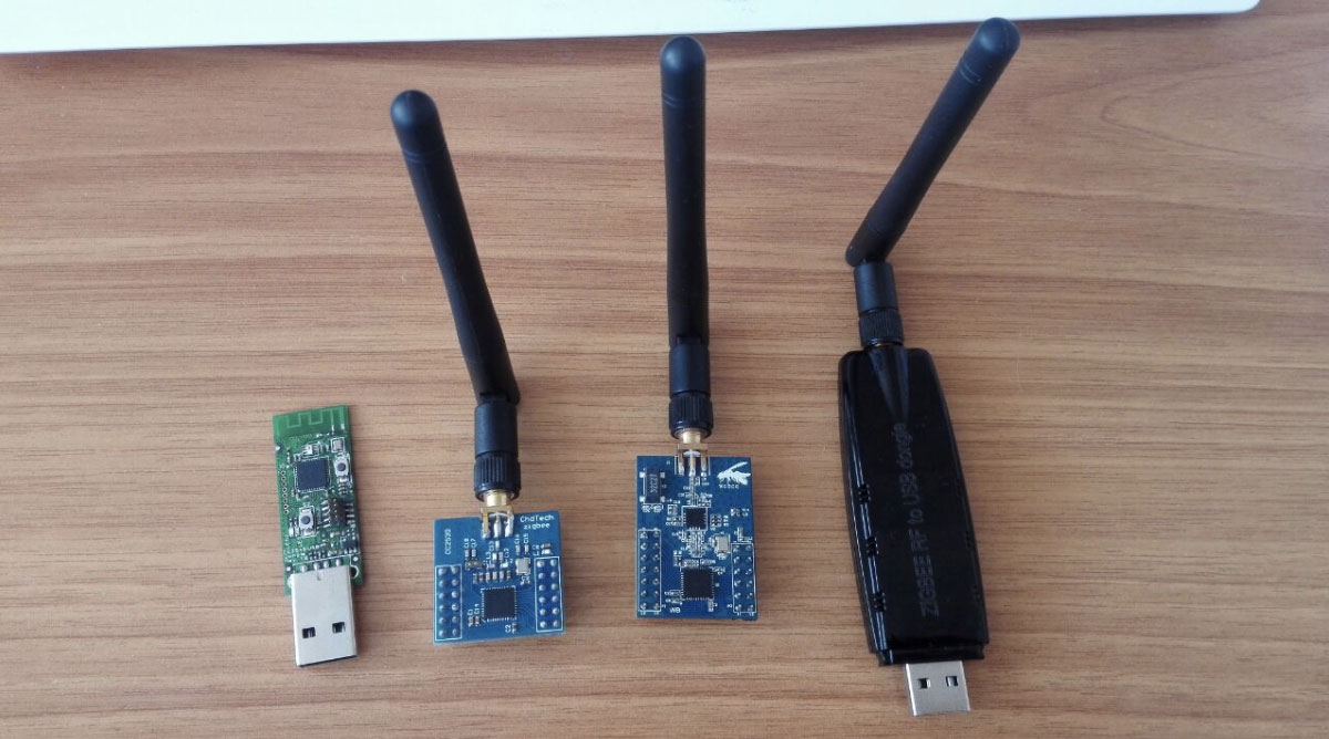
I FINALLY got the CC2530 + RFX2401 (the device on the far right) running with a Pi 3B+ with 25 devices joined. I think the setup is similar to the CC2530 + CC2591. Here's what I did, if this info helps you, please post here so others know:
|
|
@ryanbeaton Yes. I did find issues after a few days, but its still a big improvement over the 'default' firmware, so I strongly suggest you give it a try for a few days. @thibaultmol I've only tried the CC2531 and CC2530 + RFX2401. If you can solder (or are willing to try, its not that hard), I really suggest you go for the CC2530 + RFX2401. For me, the CC2531's range is too short and keeps dropping devices from the network, causing automations to break every so often. Having unreliable automations is far worse than no automations. |
|
anybody tried this version of CC2530+CC2591? |
|
@hoangtuit
Maybe the Door Sensors acts as a repeater? Otherwise wireless connections especially in the very crouwded 2,4 GHz band can be flaky. Also a good/clean power source can be a game changer (try a better power supply for you rpi). Try a less crouwded zigbee channel (check for interfering wlan networks). Change the orientation of you Zigbee Devices including you CCxxxx. |
|
@AnhDuc85 yes, I'm using it. works well, I'd say it's better than the previous version. @pixeldoc2000 door sensors don't act as router/repeater. |
|
@lolorc what antenna are you using for that module? |
|
@AnhDuc85 the one provided with the module. I tried with a huge 9db wifi one, but it wasn't a good idea. |
|
I have been reading several threads on alternate interfaces and in particular have interest in the RFX2401 variant. While I run on Linux, I do my flashing on Windows. I have used the CC Debugger for flashing the 2531. I have also used PlatformIO environment and esptool to flash ESP8266 boards. Looking at the schematics it looks as if RX and TX from USB/serial are routed to the 2530, but would expect some use of RESET to distinguish from normal power up vs. flashing modes. I have not seen any discussion related to this. I have seen discussion of wiring 3 pins to ground, but his one offers alternative that does not require it. My question in particular is the process to flash the RFX2401 variant of this interface. In particular from a Windows or as a second choice Debian/RPi environment. |
|
Hi @mcsSolutions , I used the Alternative flashing methods procedure to flash it. Flashing was done under Windows. The drawback is the procedure takes much time (~3hours). I also wired the 3 pins to ground. I am in no way an expert in microelectronics so I cannot answer your question about RESET usage. I will be very glad if you find a way of flashing it without soldering since I would like to have a spare one for just in case. BTW, don't forget to set rtscts to false in zigbee2mqtt configuration if using this stick. It does not work otherwise. |
|
The alternate methods link looks to me as if the flashing is actually performed via Arduino micro or ESP8266 micro. It describes the 10 pin connector that is on the 2531 but is not on my interface that contains RFX2401 so these look to be instructions for the 2531. The description indicates that "CC_RST" is associated with 5. The schematic I looked at from the supplier on Alieexpress did not have any programmable pin associated with Reset other than access to the 4 connector pads so I would not expect to be able to program without connection to this pad or with some manual intervention. How is the Adruino/ESP8266 is connected to the RFX2401 board? My ESP do not have USB connections. What specific steps were done to program the RFX2401 product? |
|
There is another link inside the documentation I sent you: here. It shows all the necessary connections. Essentially just three pins and ground need to be connected. That link shows picture with some registers but they can be skipped. I did not use them and everything worked ok. |
|
@Koenkk this would still work if you used a CP2102 and a phone charger right? Might be worth mentioning with an alternative for those not wanting to mess with AC power directly |
|
Hi All, a. CC2531 (USB stick) as coordinator and CC2530 as router. |
|
@danpowell88 thats also possible however that makes the solution unecessary big. @hoangtuit it depends, in my case the coordinator is not in an optimal place (front of my house). Therefore I've put a CC2530 router in the center of my house. Having the CC2531 as a coordinator is also a easier solution because of the USB port. Thats why I personally prefer solution A. |
|
I'm about to build one of these, based on the instructions in https://github.com/Koenkk/zigbee2mqtt/blob/dev/docs/how_tos/how_to_create_a_cc2530_router.md, but am concerned about the lack of a fuse. Is there one built into the transformer? |
|
Someone has the wiring diagram to flash the CC2530 using the Arduino's alternate flashing method? Thanks in advance! |
|
Anybody who has cc2530 + cc2591 please can you check if both antenna pins are shorted to ground for you? I have bought from Ali with GB2530 module in a plastic case and both antenna pins are shorted to the ground.
If I disconnect the antenna header and test on the board it is shorted there. The unit itself seems to work OK'sh. After penetrating couple stone walls (10m) link quality is around 40. But as I understand I get no benefit from the antenna and RF amplifier in my unit. |

Currently using a USB -> 3.3V adapter 👍 |
|
@yozik04 |
|
@mcsSolutions Thank you. I have talked to a guy more advanced in electronics. He told that it is OK that it shows short. Also oscilloscope won't show any fluctuations as it cannot measure on GHz rate. I asked this because one guy on ali has put in a feedback that he had a short somewhere. I had to check my unit as well =) |
|
This issue has been automatically marked as stale because it has not had recent activity. It will be closed if no further activity occurs. Thank you for your contributions. |
Following on from: #52, I was wondering if anyone can provide more specific links detailing the cc2530 + cc2591 setup.
For use with zigbee2mqtt, should I be using the firmware at ptvo.info or on james-fry's page?
How do you maintain power supply and connection to a Raspberry Pi 3 B+? Is there a shield available, or do we use jumper cables? Is there a link to a product or jumper cabling guide to help achieve this connection?
For those who have used any of the 4 devices here, how do you normally position them? I have 2 CC2531s I plan to use as routers, and the cc2530 + cc2591 as a coordinator on my Pi. I understand that the cc2530 + cc2591 is more sensitive and can 'hear' better, so the CC2531's effective range is increased. But how big is the range increase? Is it only 2 - 3 meters, or more?
And just a random question, but has anyone considered using the RS232 based on the CC2630 chip? It claims to have a 1.6KM range!
The text was updated successfully, but these errors were encountered: